
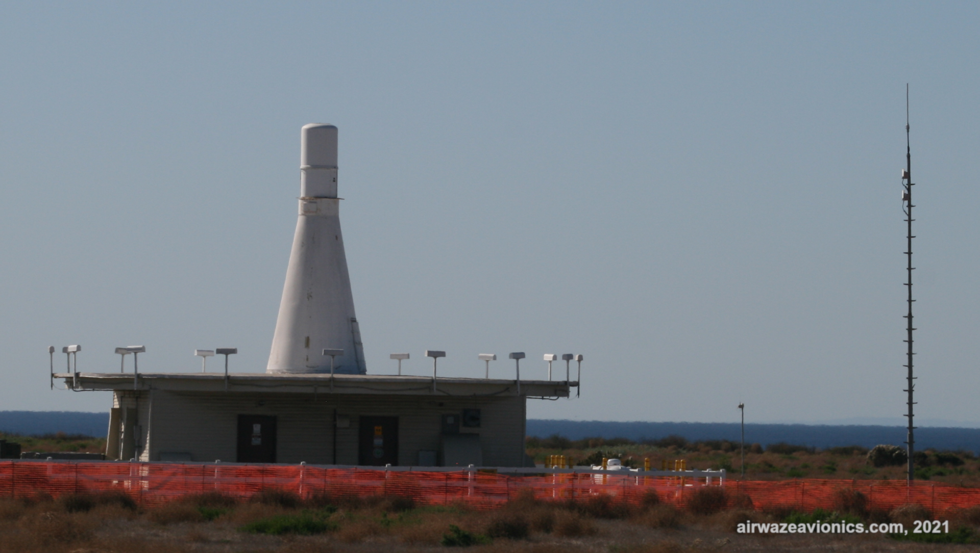
DME is an acronym for Distance Measuring Equipment. DME is a radio navigational aide used by aircraft to determine the distance to or distance from a radio beacon. Technically speaking, DME is a transponding RADAR system. RADAR is an acronym for RAdio Detection And Ranging. The system is a transponding system because it is based on a system of interrogations and replies. DME reports the slant range distance from the aircraft to the beacon on the ground.
History
The DME system was developed during WWII by the Allies. It was developed to aid in troop, supply, and bomb drops. The code name for the DME system during the war was “Rebecca-Eureka”. “Rebecca” reportedly derived from the system’s description as RAdio BEaCon detection. “Eureka”, meaning “I’ve got it”, represented the transponding response of the beacon to an interrogation from the aircraft.
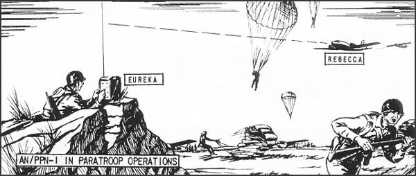
Early attempts at using traditional radar to detect ground-based targets were unsuccessful. These early attempts were unable to discriminate targets from large amounts of ground return or radar clutter. This led designers to develop a transponding or beacon system. The beacon replies would occur on a secondary frequency and thus the airborne receiver would not be swamped by ground returns from the primary transmit frequency.
Modern DME systems remain very similar in operation to the early “Rebecca-Eureka “system.
Modern systems are used in both Civil and Military applications. The military uses DME as part of TACAN (TACtical Air Navigation) stations. DME is often co-located with civil VORs and is used as part of the ILS (Instrument Landing System). In situations where the DME is co-located with VOR or Localizer installations, there are frequency pairings that allow for simultaneous tuning of the DME receiver by simply tuning to the VOR or LOC frequency. This tuning is handled automatically by the radio. VORs operate in the VHF band from 108 to 118MHz. DME operates in the UHF band from 978 to 1213MHz.
Some stand alone beacons may exist and can be tuned to directly or via the associated UHF frequency pairing.
Slant Range vs Ground Distance
Slant range is another way of saying that the distance reported is the actual straight line distance to the station as opposed to the distance across the ground to the station. Think of slant range as the hypotenuse of a right triangle and the ground distance as the length of the leg along the x-axis.
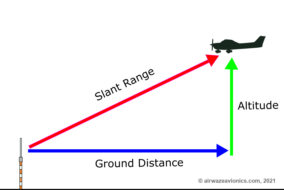
With this in mind, note that the percent error in the reported slant range distance vs ground distance is minimized when the aircraft is further from the station and becomes larger as the aircraft approaches the station.
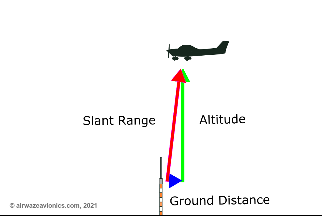
In the extreme case, as the aircraft is directly over the beacon, the distance to the beacon will be equivalent to the aircraft altitude over the beacon. Because slant range is by definition the straight line distance to the station, the system is necessarily a “line-of-sight” system. Beacons over the horizon may not report accurately or may not reply at all.
Theory of Operation
The transponding DME system consists of two main parts. The first part is the airborne interrogating transceiver. The second part is the ground based responding transceiver. The airborne transceiver interrogates on frequency A and the ground based beacon responds on frequency B. As mentioned above, this results in the airborne receiver not being overwhelmed or desensitized by ground returns on frequency A.
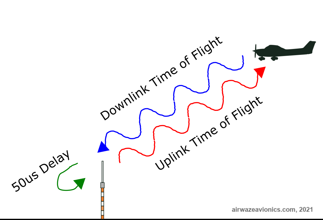
DME relies on the principle of time-of-flight (TOF) of radio waves to function. Radio pulse pairs are sent out from the interrogator (“Rebecca”) on an RF carrier frequency (Frequency A). The beacon (“Eureka”) receives the pulse pairs on the RF frequency A, waits for an allotted amount of time (typically 50us) and replies with its own pulse pair on a new frequency (Frequency B) either 64 MHz above or below the Rebecca RF carrier frequency. Rebecca then uses the round-trip delay between sending and receiving pulses (minus the 50us beacon delay ) to calculate the slant range (line of sight) distance to the station.
The equation to calculate slant range distance is as follows:
Slant_Distance = (ToF-50us)/(12.359us/nm round trip)
where ToF is the round-trip Time-of-Fight of the radio wave expressed in microseconds. The constant 12.359us represents the round-trip time it takes a radio wave to propagate 1 nautical mile under standard atmospheric conditions.
Here is a sample calculation for a 25NM slant range distance.
25NM = 359us-50us/(12.359us/NM)
Solving for ground distance requires knowledge of the aircraft altitude. The formula for calculating ground distance from slant range distance and known altitude is as follows:
Ground Distance (NM) = sin( acos ((altitude/slant_distance)))*slant_distance
Here is a sample calculation for ground distance assuming 25NM slant range distance and an altitude of 9114ft (1.5NM).
Ground Distance (NM) = sin( acos ((1.5NM/25NM)))*25NM = 24.95NM
Note that there is relatively little difference between slant range and ground distance under these conditions.
Next, consider we are approaching the station while cruising at 9114ft en route to our destination. Let’s re-calculate the ground distance as slant range distance approaches our altitude.
Ground Distance (NM) = sin( acos ((1.5NM/1.6NM)))*1.6NM = ~0.6NM
The displayed distance is “off by a mile” literally. Expressed as a percentage (1-(Ground Distance/Slant Range))*100) , the error has increased from 0.2% ( or 0.05NM) at 25NM to 62.5% ( or 1NM) at 1.6NM displayed slant range.
DME message coding
One big problem with the system as described so far is that there is no way to distinguish between replies coming from the beacon. If multiple aircraft query the same beacon, how do they distinguish which reply is for them and which ones they should ignore?
The solution is that each individual interrogator (“Rebecca”) intentionally injects a random but quantifiable time shift between successive interrogations to the beacon. Over a series of interrogations, these random timing shifts result in a unique pattern or code that can be used to look for beacon replies with the same timing shifts. This is known as injecting “jitter” in the timing of the interrogation.
What if there is no beacon nearby?
A second problem with the system as described in the paragraphs above is that the interrogator will continuously send out pulses, even if there is no beacon in range. This will result in wear and tear on the system and pre-mature failure of high power components.
To fix this second problem, the system employs an “Auto-Standby” mode. In this mode, the interrogator will automatically stop sending out pulses after it fails to receive replies from the beacon. The interrogations will not resume until the receiver receives a pre-determined number of replies. This is possible because the beacons are designed to send out random replies even in the absence of interrogations from aircraft. Collectively, these automatic replies are referred to as “squitter”. The interrogator automatically begins periodic interrogations after it receives a pre-determined number of squitter replies in a given time period. For example, the threshold for exiting auto-standby might be 300 auto-replies per second.