The instrument landing system (ILS) is a radio frequency (RF) navigation system used to aid aircraft in approaching a runway for landing during periods of reduced visibility. The system consists of multiple ground-based transmitters, airborne receivers and cockpit displays. The ground based transmitters produce beams of RF radiation that are decoded by airborne receivers to indicate flight path and distance to the runway. The ground based components are called the localizer, glideslope, outer marker, middle marker and inner marker beacons.
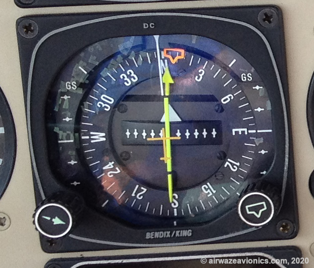
The localizer is used to transmit course information. It can be thought of as a VOR having a single radial aligned with the runway centerline. In fact, the VOR indicator often serves the dual purpose of displaying both the VOR radial and localizer course information. Nonetheless, the actual transmitted signal characteristics are different between the localizer and VOR and it’s helpful to note a few differences between the two. (Click here to learn how a VOR works) First, note that the OBS knob on the VOR indicator doesn’t effect the CDI when the NAV radio is tuned to a localizer frequency. Second, note that the CDI is more sensitive when tuned to a localizer than when tuned to a VOR. The course offset dots on the display typically represent 0.5 degrees when displaying a localizer vs 2 degrees when displaying a VOR radial. This results in a total display window of ±2.5 degrees for the localizer and ±10 degrees for the VOR. The CDI will move to the left and right of course to provide steering information to the pilot. A CDI to the right of center indicates the pilot should steer the aircraft to the right to intercept the extended runway centerline. A CDI left of center indicates the pilot should steer left and a CDI that’s centered means the aircraft is on-course to the runway.
The glideslope transmitter is used to send vertical flightpath information. Vertical flightpath information is also typically displayed on the VOR indicator using a secondary CDI. The glideslope CDI is horizontal and moves from bottom to top on the display to indicate whether the aircraft is too high, too low or on the correct glidepath to the runway.
A horizontal situation indicator or HSI may also be used to show both localizer and glideslope information. In this case, the localizer information is shown via the CDI in the middle of the course pointer ( similar to a VOR radial indication ). The glideslope information is usually shown by a pointer that moves vertically along a scale on the side(s) of the instrument. The aircraft is on-course and glidepath when the CDI is centered on the course pointer and the GS pointer is centered on the vertical scale.
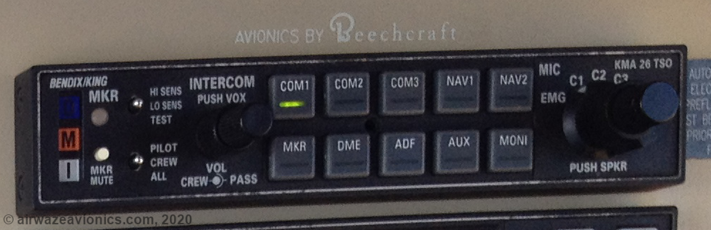
Marker beacons are a set of transmitters located along the extended runway centerline. They send out narrowly-focused vertically-oriented radio beams. As the aircraft passes over each beam, a different colored indicator illuminates in the cockpit along with a unique audible tone sequence. These audible and visual cues provide the pilot with situational awareness regarding the aircraft’s progress along the instrument approach.
Though they are technically part of the ILS system, marker beacons have begun to be phased out by the FAA in the United States. At the time of this writing, It is very rare to find a middle marker in use. Outer markers are still in use in small numbers but the bulk of the beacons still in use are inner markers. This is not too surprising due to the role inner markers play in CATII and CATIII approaches; However, it could also be due to lower operating costs of these beacons. They are likely located on airport property ( avoiding real estate entanglements ) and can be conveniently serviced by airport personnel.
How does an ILS localizer work?
As mentioned above, the localizer transmits directional RF waves out along the extended runway centerline. In fact, the localizer actually sends out two beams. A left beam and a right beam ( from an approaching aircrafts perspective). The left and right side beams are adjusted so they just barely overlap along the exact runway centerline. The left side beam is a horizontally polarized (similar to a VOR) VHF carrier signal that is AM modulated with a 90Hz sinusoidal or continuous wave (“CW”) signal. The right side beam is also a horizontally polarized VHF carrier signal but it is AM modulated with a 150Hz CW signal. Thus, an aircraft to the left of centerline will predominately receive the 90Hz modulated signal and the CDI will move right to indicate “steer to the right” to intercept the runway approach course. An aircraft to the right of course will predominately receive the 150Hz modulated signal and the CDI will move left to indicate “steer to the left” to intercept the runway approach course. Along the centerline of the approach course, the receiver reads equal amounts of 90Hz and 150Hz signals and the CDI stays centered indicating the aircraft is on-course.
How does an ILS glideslope work?
Similar to the localizer, the glideslope transmitter also sends RF waves out along the runway approach course; however, glideslope beams are angled up into the air ( typically at an angle of 2.5 to 3 degrees). The glideslope transmitter signal is a vertically polarized, AM modulated, UHF (328-335MHz) RF carrier that is modulated by 90 and 150Hz baseband signals. Through the interaction of direct and reflected radio waves, beams of radio energy are formed along the approach course. These beams can be divided into three main areas of interest. The first area is along the desired glidepath. This is the area we want the plane to track down to the runway. In this area, there are equal amounts of 90 and 150Hz AM sideband energy. The second area is the area above the desired glidepath. In this area, there is a greater amount of 90Hz AM sideband energy. The third area is the area below the desired glidepath. In this area, there is a greater amount of 150Hz AM sideband energy. The areas are not strictly discrete and there is actually a continuum of states between each area. The airborne receiver tracks an AM signal metric called depth of modulation to determine not just that the aircraft is above or below the glideslope but how far it is above or below the glidepath. When the receiver picks up more 150Hz signal, the aircraft is too low and the CDI will move up an amount consistent with the change in depth of modulation of the 150Hz AM sideband. This indicates the pilot should “climb” ( or at least stop descending ) to intercept the glidepath. When the receiver picks up more 90Hz modulated signal, the aircraft is too high and the CDI will move down an amount consistent with the change in depth of modulation of the 90Hz AM sideband. This indicates the pilot should “descend” to intercept the glidepath. When the glidepath CDI is stable in the center of the display, this indicates the aircraft is receiving equal amounts of 90 and 150Hz signal and is descending along the correct glidepath towards the runway.
How does an ILS marker beacon work?
Marker beacons send focused RF waves upwards into the sky and are located along the extended runway centerline or approach course. Their transmitters use directional antennas to confine radiated signals to the area directly over the marker beacon. This is crucial since the marker beacon’s primary function is to provide distance information to aircraft on the approach. An uncontrolled radiation pattern could result in aircraft indicating incorrect position along the approach.
The outer marker is typically positioned at 4.5 nautical miles (4-7 nm is allowed) from the runway threshold and illuminates a blue flashing light in the cockpit. The outer marker transmits its signal on a 75MHz carrier that is AM modulated with a 400Hz CW tone. The carrier is keyed to provide an audible signal of two morse-code-type “dashes” per second. The outer marker will often coincide with the final approach fix (FAF) for the approach.
The middle marker is typically located 3500ft from the runway threshold and illuminates an amber light in the cockpit. The middle marker transmits on a 75MHz carrier that is AM modulated with a 1300Hz CW tone. The carrier is keyed to provide an audible signal of morse-code-type “dash-dot” pairs at 95 times per minute. Middle marker placement is designed to coincide with a 200ft decision height on the glidepath.
The inner marker is located at or very close to the runway threshold (typically 0.1 miles) and illuminates a white light in the cockpit. The inner marker transmits on a 75MHz carrier that is AM modulated with a 3000Hz CW tone. The carrier is keyed to provide morse-code-type “dots” at 6 times per second. The inner marker is only required for CATII and CATIII approaches and is installed to coincide with a decision height of ≤100ft on the glidepath.
Keep in mind that each ILS installation is unique. The distances and decision heights listed above are typical values but they could change based on the unique terrain and obstacle features around a particular runway.
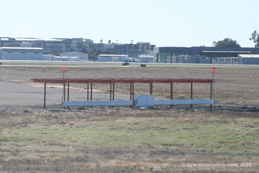
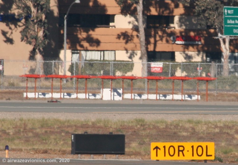
What kind of antennas does an ILS localizer use?
The localizer transmitter uses an array of directional antennas to send out its signals. The antennas are generally arranged in a linear array pattern. The array is located at the far end of the approach runway and runs perpendicular to the direction of the runway ( i.e. across the runway) The antenna elements may be of any directional type but are often either the V-Ring or Log Periodic Dipole (LPD) style antennas. An example of this type of antenna is shown in the photo below.
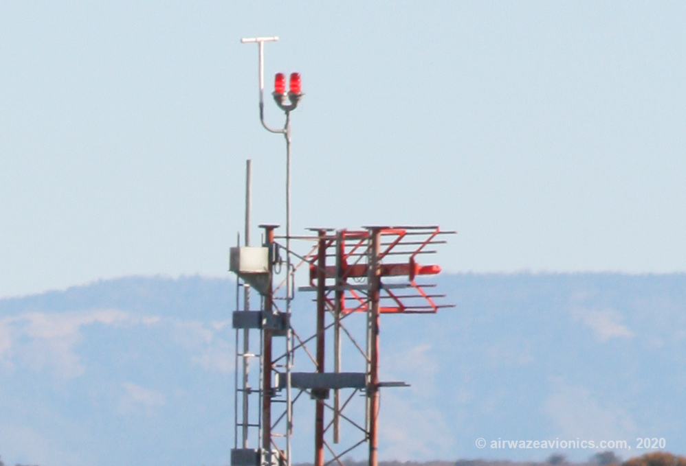
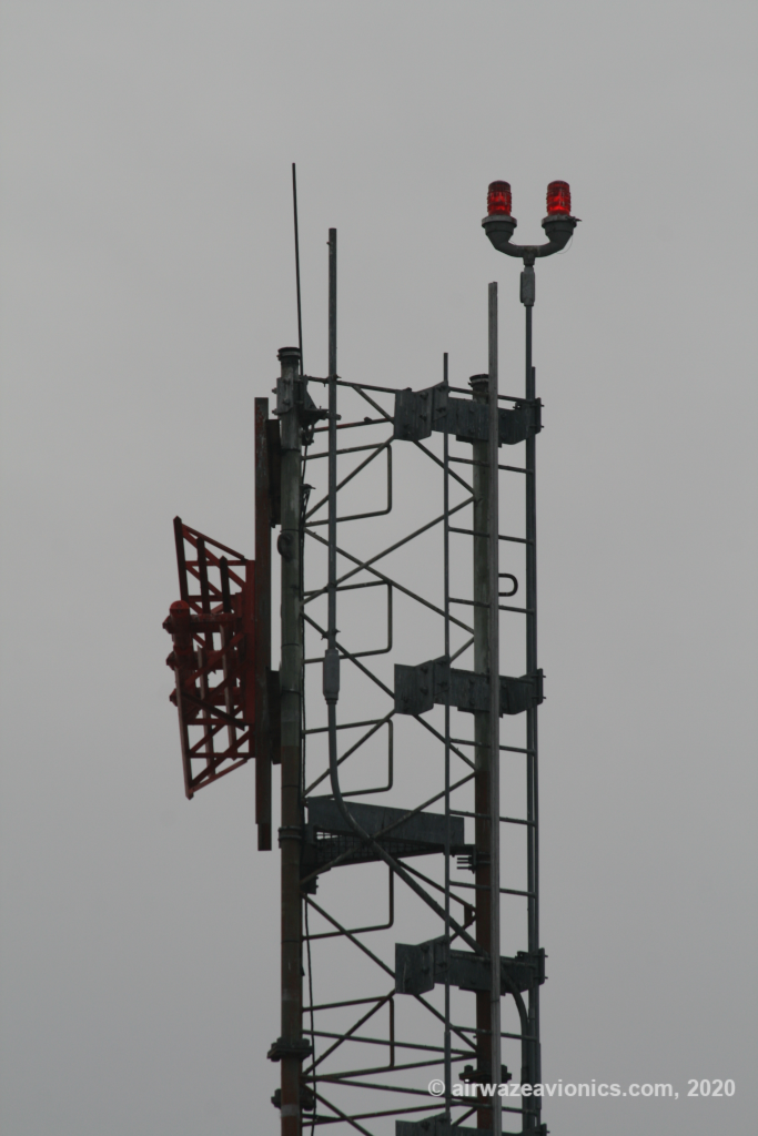
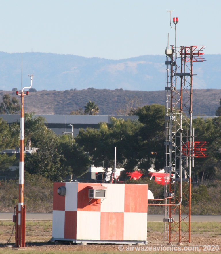
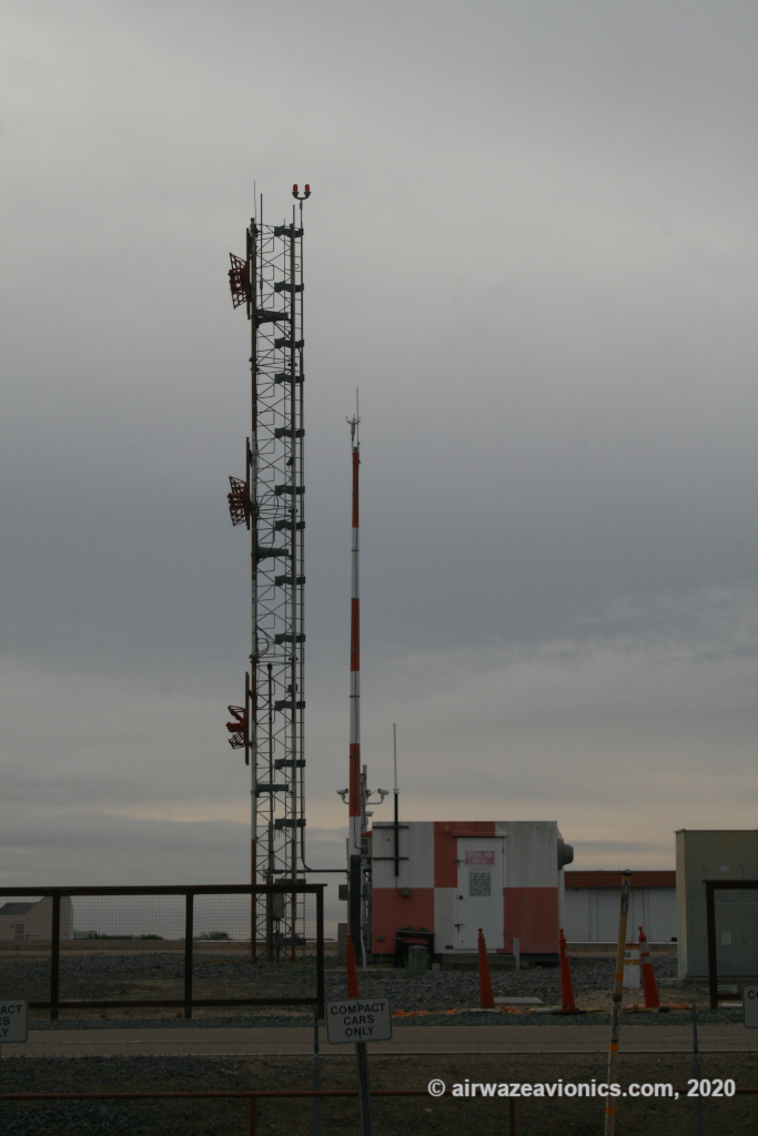
What kind of antennas does an ILS glideslope transmitter use?
There are actually many different types of glideslope antennas. One of the more common designs found in the United States is a 90 degree reflector type which is fed by 3 collinear dipole elements. An example of this type of antenna is the model 300A manufactured by dB Systems Inc. Click here to view specifications for this antenna on dB Systems Inc webpage. Two examples of this type of antenna are shown below.