Introduction
This page aims to answer the question: How does a VOR work? VHF Omnidirectional Range (VOR) is radio frequency based Navigational Aid (NAVAID) system used to provide course guidance to pilots. It has formed the backbone of the National Airspace System (NAS) in the United States and around the world since 1946 and is used by all types of aircraft including civil, commercial and military.
As its name implies, the VOR system operates in the Very High Frequency (VHF) range and consists of a ground based transmitter and an airborne receiver. The system is designed to allow pilots operating an airborne receiver to determine their aircraft’s position relative to the ground based transmitter.
VOR System Components
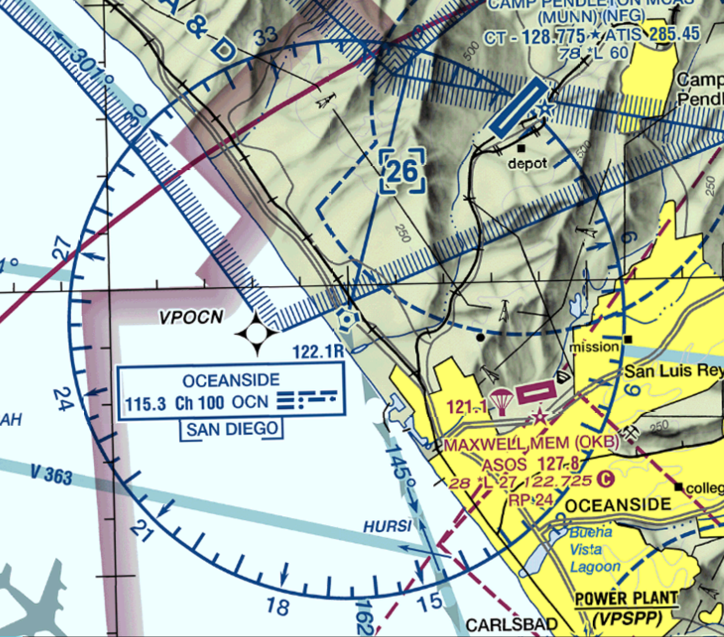
Ground based transmitter geographic locations are well documented on aviation charts. This allows pilots to navigate along pre-determined highways in the sky called “airways”. Navigating along this system of airways at specified safe altitudes provides obstacle and terrain clearance for pilots flying at night or during other periods of low visibility. Additionally, these airways provide a convenient way for pilots to communicate their intended flight plan to air traffic control or flight service. If search and rescue is required, there is a well defined search area for rescue services to focus on.
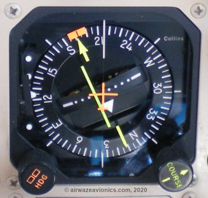
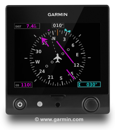
The VOR cockpit display is commonly called the VOR Indicator or Omni-Bearing Indicator. The indicator consists of a compass card and a vertical needle referred to as the Course Deviation Indicator (CDI) . The compass card can be adjusted by rotating the Omni-Bearing Selector (OBS) knob on the side of the display. The desired course is then set under the tip of the arrow or the “lubber line” at the 12 o-clock position on the bezel of the compass card. There are several different types of VOR indicators: VOR course only, VOR/ILS with Glideslope and the Horizontal Situation Indicator. The HSI is actually a combination of two instruments, the Heading Indicator and the VOR/ILS/Glideslope Indicator. On the HSI the OBS knob is replaced by the COURSE knob and a heading select knob (HDG) is added for autopilot functions. Finally there are digital instruments that can approximate the displays of the VOR and HSI indicators. The common theme is that there is an OBS/COURSE knob and CDI on all VOR Indicators.
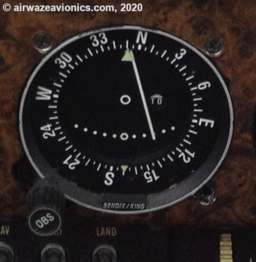
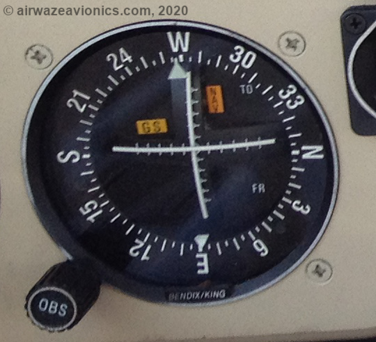
The cockpit display also includes a TO-FROM indicator. This indication is intended to disambiguate whether the aircraft is heading TO or FROM the station on the selected course. The TO-FROM indication is displayed in a window on the compass card and may literally be the words TO or FROM or alternatively an arrowhead pointing up (towards) or down (away).
The CDI needle is free to swing from left to right and indicates whether the aircraft is on the selected course. The needle will be positioned in the middle of the display in a perfectly vertical orientation when the aircraft is on the desired course. The display will also typically include a set of dots or tick marks in the center on either side of the course center line. Each dot represents 2 degrees of deviation from the desired course. The maximum displayed deviation is 10 degrees to the left or right. The CDI will “peg” or limit itself to the left or right extents of the display when the course deviation is beyond 10 degrees.

Another piece of the airborne system is the navigational (nav) radio control head. This is typically located on the “radio stack” and is often a combination nav and communications (comm) radio. The example shown on this page is a Bendix/King KX155A dual nav/comm radio. The left half of the control head is the comm portion and the right half is the nav portion. Each side displays two frequencies, one active frequency and one standby frequency. This allows the pilot to have the radio tuned to two different frequencies and easily toggle between them using the swap frequency buttons (buttons with two-way arrows on them). Also note each radio has separate frequency selector knobs and volume/squelch control knobs.
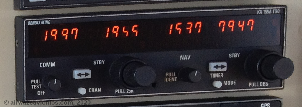
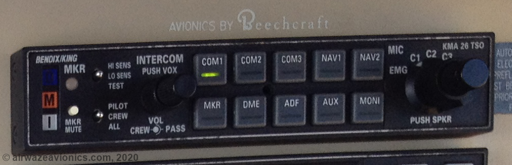
The pilot uses the audio panel to select which audio source to hear through the headphones. Pilots can identify VORs by unique morse code identifiers (more on this below). Pilots identify a VOR by pulling the “squelch” knob out and adjusting volume on the nav radio until the VOR morse code or voice identification can be confirmed. There can be multiple audio sources routed through the headset at one time so the pilot can simultaneously monitor communications, while identifying a VOR or listening to an automated weather broadcast.
VOR Concepts
The transmitting station can be visualized as a spoked bicycle wheel with the transmitter as the center hub of the wheel. The wheel spokes represent “radials” or course directions AWAY FROM the station. These radials are coded such that they represent magnetic headings with 0 degrees representing magnetic north at each transmitter’s geographic location. Note that the geographic North pole (the point where lines of longitude converge) and the earth’s magnetic North pole (the point a compass points to) do not coincide with each other. Because the simplest form of navigation is via a magnetic compass, aircraft are equipped with a magnetic compass and all other forms of navigation are tied to this frame of reference. Under this system, the cardinal directions of N, S, E and W correspond to the 0, 180, 90 and 270 degree VOR radials respectively (this is not terribly surprising but is worth stating nonetheless).


By definition, and this is important to remember, radials are always defined as being oriented FROM the station. That is to say, the magnetic heading they take AWAY from the station. The pointy tip of the arrow goes outward from the station. By establishing which radial they are on using the VOR indicator, pilots are able to determine their position relative to the station. Further, using their known magnetic compass heading and the TO-FROM indication, they can establish themselves on a particular radial headed either towards or away from the station as desired.
For instance, an aircraft is South of the station if it is determined to be on the 180 degree radial FROM the station. Turning the aircraft to a heading of NORTH will take the aircraft TO the station while following the ground track of the 180 radial.
Navigating using VOR
To navigate using a VOR, the airborne receiver must first be tuned to the frequency of the desired ground station. After tuning to the desired frequency it is advisable to enable the audio portion of the VOR broadcast to confirm the morse code identifier matches the code for the desired station. Many pilots skip this step after completing their initial training; however, consistently identifying the tuned VOR will prevent confusion and disorientation that can lead the pilot miles off course towards an incorrect station or worse. Identifying a VOR thru its morse identifier is accomplished by enabling the NAV source on the audio panel, enabling the IDENT feature on the radio control head and adjusting the volume as necessary to hear the repeating morse code identifier.
Once the correct station is identified, the next step is to determine the aircraft’s position relative to the station. To do this, the OBS knob is rotated until the CDI centers itself in the display window AND the TO-FROM indicator reads FROM. Note the heading under the lubber line or at the tip of the arrow. The aircraft is situated on this radial FROM the station. For instance, if the CDI centered itself on course 090 FROM the station, the aircraft is located EAST of the station.
Navigating TO the station is accomplished by further rotating the OBS knob 180deg until the CDI needle is centered and the TO-FROM indicator reads TO. The indicated course is the magnetic course the aircraft must fly TO the station. Continuing the example from above, the course TO the station is 270 degrees or WEST. The pilot then turns the aircraft to the indicated heading using the magnetic compass or heading indicator. During this turn, the pilot should monitor the CDI to ensure it remains on the centerline of the desired course. If the CDI drifts to one side or the other, the pilot should make a course correction TOWARDS the CDI to bring the aircraft back on course. Resist the temptation to re-center the CDI using the OBS. This can result in “homing” in on the station as opposed to tracking a straight line to the station. Also note that prevailing winds may require the aircraft’s magnetic heading to differ slightly from the radial being tracked; however, note that as long as the CDI is centered the aircraft ground track is following the radial to the station.
To re-establish the aircraft on course, make and carefully hold an estimated wind correction angle (WCA) while monitoring the CDI. If the CDI does not move or continues to move in the wrong direction, increase the WCA by an additional 5-10 degrees until the CDI moves back towards the centerline. As the CDI approaches the centerline, begin removing WCA in small increments until the CDI stabilizes on the centerline.
A similar procedure is followed to fly away FROM a VOR on a desired radial. In this case, the only difference is that the once the aircraft is oriented relative to the station the pilot simply turns the aircraft onto the magnetic heading indicated at the tip of the arrow. For instance, if the aircraft is determined to be on the 090 radial FROM the station, the pilot simply turns to a magnetic heading of 090 to fly away FROM the station.
In both cases above of flying TO and FROM the station, it is important to note that the CDI will not indicate correctly if there is a mismatch ( > +-90 deg) between the aircraft’s magnetic heading and the course selected by the OBS on the VOR indicator. This is referred to as “reverse sensing” and will cause the CDI needle to deflect FURTHER off course if the pilot attempts to “chase” it with course corrections.
There is also a “zone of ambiguity” or “zone of confusion” at precisely +90 and -90 degrees (perpendicular) from the selected course (indicated at the tip of the arrow). In these two zones, the receiver is unable to determine if the aircraft if flying TO or FROM the station. This is to be expected since flying perpendicular to the selected course, the aircraft is in fact neither flying TO or FROM the station. In most cases, the VOR indicator will display some sort of warning flag as the aircraft passes through the zones. Note the orange colored “NAV” and “GS” flags being displayed on the VOR indicator below. These are displayed and the CDI and GS needles will typically return to center when no signal is being received.
Since the radials are emanating FROM the VOR, as they propagate further from the VOR, the physical distance between them increases (just like the spokes on the bicycle wheel shown above). Another way to think about this is that the radials become wider the further they are from the station. This has the effect of making the CDI LESS sensitive to small course deviations and winds when the aircraft is FAR from the station. When the aircraft is CLOSE to the station the physical distance between the radials is reduced making the CDI more sensitive to small course deviations and winds. In fact, as the the aircraft gets very close to and actually flies OVER the VOR, the aircraft enters the so-called “cone of confusion”. In this zone, the radials become so close together that the CDI bounces around without giving a stable indication. For this reason, it is important as the aircraft approaches the station, that the pilot NOT chase the CDI but rather hold course and WCA until the VOR is passed. The CDI will re-center itself with a FROM indication ( flipped from TO to FROM as the station is passed) and the pilot can continue to make minor course corrections as indicated by the CDI (the instrument will still be configured for normal sensing).
How Does a VOR work?
VOR ground stations make use of the electromagnetic principles of antenna arrays and analog signal modulation to produce two independent signals. One of the signals propagates uniformly in all directions while the other signal is directional and propagates in a continuously rotating pattern. This pattern is routinely compared to that of a lighthouse. The omnidirectional beacon flashes each time the lighthouse points north and the variable signal flashes as the light sweeps through the observers angle from the station. The time difference between flashes corresponds to the angle or “radial” from the station. In actual VOR systems, the receiver is not sensing the time difference but rather the phase difference between the reference signal and the variable signals.
What do we mean by the “phase difference” between the signals?
Fixed frequency sinusoidal signals, such as those used by VORs, can be visualized as vectors rotating around a point (called the “origin”) at a specified frequency. In the case of conventional VOR systems, that frequency is 30Hz or 30 revolutions per second. Given that the vector is rotating 30 full cycles or 360deg every second, we have 360 x 30 = 10,800deg/sec OR 1 degree every 92.6us. It takes 360 x 92.6us OR 33.33ms to complete a single rotation. This is called the “period” of the signal. Note that the frequency of the signal is equivalent to 1/Period = 1/33.33ms = 30Hz. The signal is thus “periodic” and repeats itself every 33.33ms. As a vector is spinning around, the angle that it points at is known as its “phase” angle. With this in mind, consider the case of two independent vectors named reference and variable. If we were to start the reference vector but DELAY the start of the variable vector for 16.7ms (which is roughly half of 33.33ms), the difference in phase angle between the two vectors would be 180deg because the reference vector would have reached its 180 phase angle while the variable vector would just be starting out at 0 deg.
VOR transmitters adjust the phase difference between their own reference and variable signals such that depending on the angle the receiver is from the station, this phase difference corresponds to the magnetic bearing from the station. The simulation below illustrates the concept of a phase delay that is dependent on magnetic bearing from the station. Magnetic North is located at the 12 o-clock position in the simulation. The blue reference signal is uniform and constant in all directions while the red signal has an ever-increasing phase delay as the angle from the station increases. Note that the simulation depicts only a single propagating wavefront. There are additional wavefronts emanating from the VOR transmitter constantly such that there is always 0deg of phase difference at the 0 deg magnetic bearing. This is effectively how the VOR system works but of course there are details to explore and I get into those below.
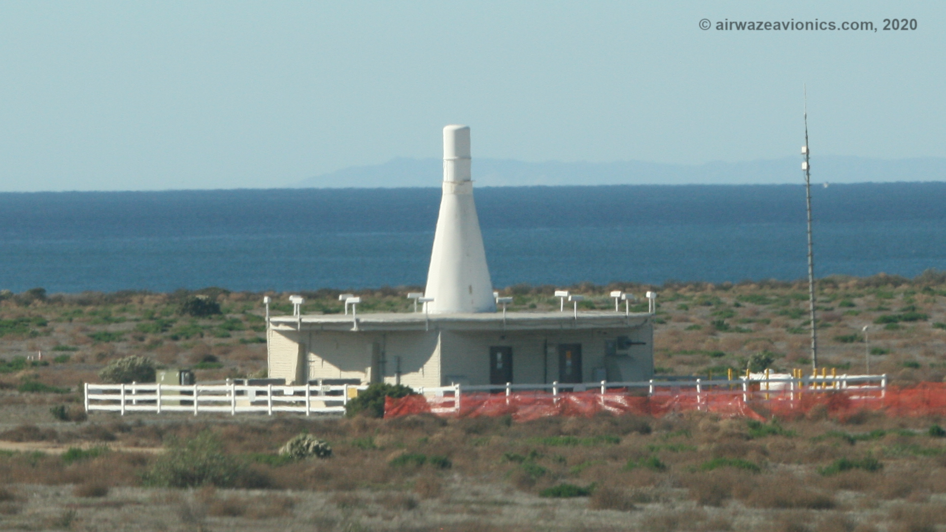
VOR Antennas
The antennas on the VOR ground station are a very specific type of antenna called an Alford Loop, named after its inventor Andrew Alford. The primary design feature of these antennas is that they are very effective at radiating horizontally polarized signals. Horizontally polarized radiation is required to ensure the most accurate VOR signal reception and decoding. Early radio beacon navigation tests using other types of antennas showed the potential for decoding errors based on aircraft orientation. You can read more details of this in Alford’s patent filing “Antenna System, US2283897”.
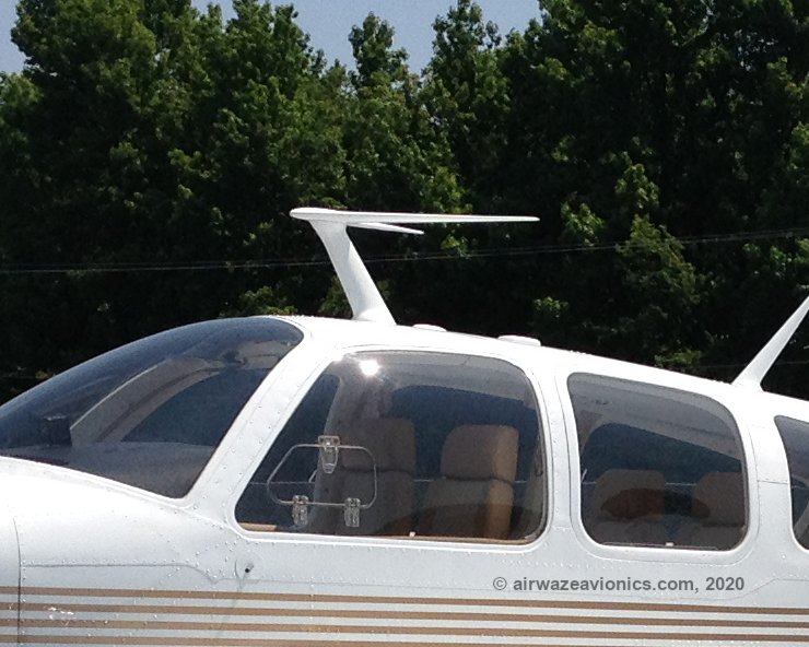
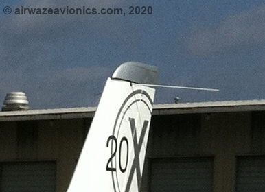
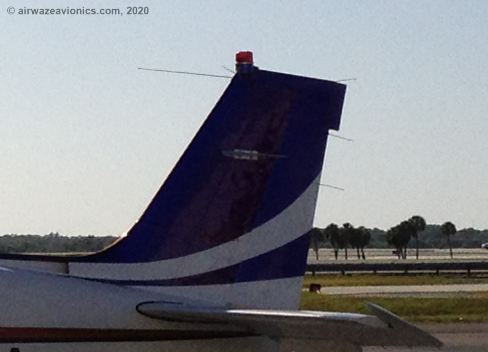
The airborne antennas are much simpler dipole-style antennas. They are usually seen on the vertical stabilizer as two small antenna masts pointing backwards or forwards in a V-shaped pattern. Some aircraft such as the V-tail Bonanza (that don’t have a vertical stabilizer) will have the antenna mounted in another location such as on top of the fuselage. Note that these antennas are mounted in the horizontal plane (left/right as opposed to up/down) to align with the horizontally polarized waveforms from the VOR ground station.
What do we mean “horizontally polarized” waveforms?
Radio wave radiation can be visualized as ripples from a drop of water on a still pond. There is an initial excitation, followed by a wave front with peaks and valleys that radiate outwardly in a perfectly uniform pattern until the energy dissipates. Thinking of the peaks and valleys of the ripples, this is analogous to the electric field of a radio wave. In the water droplet analogy, the ripple peaks and valleys exist in the vertical plane and thus would be considered to be vertically polarized. It is the same way for radio waves, when the electric field variations are in the vertical plane, the wave is said to be vertically polarized. Thinking of VOR radio waves, the electric field in these waves is confined to the horizontal axis. For this reason they are said to be horizontally polarized signals. To maximize received signal strength and improve signal to noise ratio, receiver antennas are typically oriented such that they very closely align with the direction of varying electric field from a distant transmitter. This helps explain the difference in orientation between some of the different antennas on aircraft and particularly why VOR antennas are oriented side-to-side vs up-and-down. There are some excellent resources on the web that explain the physics of electromagnetic wave propagation. I refer the reader to these resources if a more detailed explanation is desired or required.
VOR Reference and Variable Signals
There are two different signals being sent out of a VOR simultaneously. They are the reference signal and the variable signal. The reference signal as its name implies, is used as a reference to compare with the variable signal. The reference signal is calibrated such that its 0 degree phase point coincides with magnetic north at the station’s geographic location. Specifically, the reference signal is a 30Hz FM modulated signal on a 9960Hz subcarrier (+-480Hz modulation index). This subcarrier is up-converted to the VHF band through an AM modulator resulting in a conventional dual sideband full carrier AM wave.
The second signal is the variable signal. The variable signal is a signal whose phase varies according to the bearing or angle an observer is from the station. The difference in phase angle between the reference and the variable signals is indicative of the bearing the observer is from the station. Specifically, the variable signal is a 30Hz AM modulated dual sideband suppressed carrier (DSBSC) signal. This signal is split into quadrature (I and Q), up converted to the VHF band and fed to the antenna array such that the phasing at each antenna is 90 degrees out of phase from its neighbors. This combination of signal phasing and physical antenna relationships results in a radiation pattern resembling a figure 8 that rotates in the horizontal axis at a rate of 30Hz.
Antenna Radiation Pattern
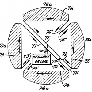
In the simplest conventional VOR implementation, there are 4 square Alford Loop antennas arranged in a 2×2 square pattern. They are identified according to their locations as northeast, southeast, southwest and northwest antennas. The antenna feed network is designed to allow simultaneous feeding of all 4 antennas with both the reference signal and the variable signal. Further, the feed network is designed to allow the reference signal to be fed to all antennas in-phase while the variable signal is applied to each antenna with a corresponding phase or electrical delay. This results in the reference signal propagating with an omni-directional radiation pattern and the variable signal propagating with a rotating figure 8 radiation pattern. It is important to note that the rotation of the variable signal’s pattern is due solely to the electrical characteristics of the signal and not to any mechanical switching or rotation of the antennas. Since the reference and variable signals are operating on the same carrier frequency, their radiation patterns combine in space (spatial modulation) to form a composite pattern called a limacon. The limacon pattern also rotates at 30Hz and simultaneously conveys information about both the reference and variable signals. This is made possible by the fact that the data for each signal is carried orthogonally or “independently” on the carrier as FM (reference) and AM (variable) information.
What do we mean “Orthogonal” signals?
Orthogonal is defined as being “at right angles to” or “statistically independent”. Both of these definitions apply to the VOR limacon signal. To illustrate, consider a cartesian reference plane having an x and y axis. Imagine a vector emanating from the origin at a 45 degree angle. Now, draw a vertical line straight up from the x axis (forming a triangle) to the tip of the vector and note its length. This is known as the y component of the vector. Next, draw a horizontal line from the y axis to the tip of the vector (forming a second triangle) and note its length. This is known as the x component. Our main 45 degree vector is called a “resultant” vector as it is the “result” of adding the orthogonal x and y component vectors together. Now imagine how the resultant would move if either the x or y component vectors were varied. It is possible to move x and y independently or together to have an effect on the resultant vector behavior; however, x and y components can never change each other. That is to say, changing x will never have an effect on y and vice versa. By definition then, the x and y components are orthogonal to each other. This property of signals is used extensively in communications and digital signal processing.
Considering our composite limacon radiation pattern, the reference and variable information is said to be orthogonal since the reference information is encoded via frequency modulation and the variable information is encoded via amplitude modulation. As such, variations in either signal don’t have an effect on the other, even though they are present on the same VHF carrier.
The simulation below illustrates how the AM portion of the variable signal results from the rotation of the limacon radiation pattern. The amplitude graph (shown in the lower left corner) depicts the received VOR signal strength at the aircraft location. Note that depending on the location of the aircraft around the VOR, the “peak” that it experiences will occur during a different “phase” of rotation of the limacon pattern. In the simulation below, the peak amplitude occurs at the 270deg phase point since the aircraft is situated on the 270deg radial from the station.
What do we mean AM and FM signals?
AM is short for amplitude modulation and FM is short for frequency modulation. These are two different way’s of encoding information onto a signal to be transmitted. You’re probably familiar with AM and FM broadcast radio stations. You might also recall that AM radio stations typically contain more noise and static than FM stations. This is related to the fundamental difference in the way these stations are sending information over the air. AM stations are encoding information in the amplitude or power level of the transmitted signals. All sorts of natural and man-made phenomenon can affect the level of the signal as it travels through the atmosphere ( i.e. Lightning and the electric alternator on your car ). This causes noise and static in the received signal. On the other hand, FM stations encode information in the frequency of the signal being transmitted. Those man-made and natural phenomenon still affect the signal level of the FM signal but since there is no information in that part of the signal, the sounds you hear are clear of noise and static. FM stations are not completely immune from signal impairments but they are in general much less of an issue.
As noted in the section above on the reference and variable signals, the VOR transmitter is actually sending information over the air using AM modulation. Recall the reference signal is carried on an FM modulated 9960Hz subcarrier. The subcarrier is then upconverted by the VHF AM modulator for transmission over the air. At the receiver, the VHF AM signal is demodulated resulting in the FM subcarrier being downconverted back to its original low frequency (this means it is mixed from the VHF band at ~118MHz down to ~10kHz) . The FM subcarrier is then demodulated to extract the 30Hz reference signal. This is the first of two 30Hz signals the VOR receiver needs to determine its location.
As shown in the simulation above, the AM modulated variable signal results from the rotating nature of the limacon radiation pattern. Thus, the amplitude of the VHF carrier frequency ( called the envelope of the signal ) results in a 30Hz sinusoidal pattern. After demodulating or extracting this envelope (this is our 30Hz variable signal) from the received VHF signal, the VOR receiver now has the second and final 30Hz signal required to determine its location.
Finally, The two decoded 30Hz signals (reference and variable) are compared and the phase difference between the two indicates the angle the receiver is from the station. For instance, a 90 degree phase shift between signals indicates the aircraft is on the 090 radial or is due East of the station.
That wraps up our discussion of how the VOR works and what are the primary technologies that make VOR navigation possible. We’ve talked about the VOR system from top to bottom including antennas, antenna polarization, radiation patterns, AM/FM modulation, signal concepts like phase and orthogonality and also how pilots navigate using the system.
Next, we’ll discuss the VOR’s cousins: the Localizer and the Glideslope that make up the ILS or Instrument Landing System.